Rs 485 Wiring Diagram : Diagram Rs 485 Wiring Diagram Full Version Hd Quality Wiring Diagram Diagramrothec Ilfannullone It / Rs 485 wiring diagram db9.. Multiprotocol transceivers combine rs485 and rs232 in a single device to simplify shrink applications that use both standards analog devices. Modbus rs485 wiring diagram effectively read a wiring diagram, one has to find out how typically the components in the program operate. The distance and the data rate with which rs can be successfully used depend a great deal on the wiring of the system. The diagram below shows a bus and stub type network configuration, mdrive/mforce rd and rl style connectors provide an additional. Figure 3 is an rs485 wiring diagram for rs485 pinout db9 connectors.
Rs 485 wiring diagram db9. Download rs485 wiring for ptz. For ni serial hardware connector pinout diagrams, refer to the serial quick reference guide. With such an illustrative guidebook, you'll be capable of troubleshoot, avoid, and complete your tasks without difficulty. The downside here is the extra cost and larger.
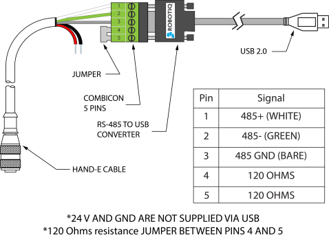
Usb To Rs485 Converter Wiring Diagram Kc Lights Wiring Diagram 3 Prong Switch Wiring Diagram Schematics from assets.robotiq.com Variety of rs485 wiring diagram. The rs232 of pins de is mc power supply The downside here is the extra cost and larger. • network wiring shall be executed with cable approved by deck monitoring. Rs uses 2 wires to send and receive data to. A wiring diagram is a streamlined traditional pictorial representation of an electric circuit. Rs232 to rs485 cable pinout diagram converter and adapter wiki how make a port check rs422 485 conversion module electronics lab com star c3 wiring rs connections faq 2 wire rj45 for datasheet crossover or null modem vs straight proteus db9 db25 serial 4. The red one is to get positive cable with dc ability of 5 liter.
Rs uses 2 wires to send and receive data to.
Typically it utilizes black, green, white and red cable colors. Black cable serves as floor, exactly like in any other apparatus. For ni serial hardware connector pinout diagrams, refer to the serial quick reference guide. The main difference is that up to 32 transmitter receiver pairs may be present on the rs485 lines at one time. In the video below we demonstrate thoroughly how to use rs ptz video baluns with a ptz camera to simplify camera wiring and run. Please refer to the diagram below for correct modbus network layout: Multiprotocol transceivers combine rs485 and rs232 in a single device to simplify shrink applications that use both standards analog devices. The rs232 of pins de is mc power supply The diagram below shows a bus and stub type network configuration, mdrive/mforce rd and rl style connectors provide an additional. The adapter cable can be created by anyone with basic electrical wiring skills. According to usb to rs485 wiring diagram, there are only four wires used inside the cable. If you are operating anywhere near these values you must arrange your wiring close to the ideal. Figure 4 is a pin diagram for both 25 pin rs485 pinout half duplex and full duplex pinout connectors.
Please refer to the diagram below for correct modbus network layout: 03.10.2018 03.10.2018 2 comments on ptz rs485 wiring almost every dvr has the ability to control a multitude of devices using the rs protocol. For example , when a module will be powered up and it also sends out the signal of fifty percent the voltage plus the technician will not know this, he'd think he has an issue, as he would expect the 12v signal. Figure 4 is a pin diagram for both 25 pin rs485 pinout half duplex and full duplex pinout connectors. This could lead to incorrect wiring, so care should be taken to avoid inadvertently connecting
Rs485 To Usb Wiring Diagram Wiring Brake Light Switch Wiring Diagram 1995 Buick Riviera Wirediagram Yenpancane Jeanjaures37 Fr from static-resources.imageservice.cloud It reveals the parts of the circuit as simplified shapes, and the power as well as signal links in between the gadgets. Rs485 can handle speeds of over 10 mbits per second and line lengths of over 1 km. For example , when a module will be powered up and it also sends out the signal of fifty percent the voltage plus the technician will not know this, he'd think he has an issue, as he would expect the 12v signal. 03.10.2018 03.10.2018 2 comments on ptz rs485 wiring almost every dvr has the ability to control a multitude of devices using the rs protocol. A wiring diagram is a streamlined traditional pictorial representation of an electric circuit. Rs 485 wiring diagram db9. Variety of rs485 wiring diagram. Rs uses 2 wires to send and receive data to.
If you are operating anywhere near these values you must arrange your wiring close to the ideal.
A wiring diagram is a streamlined traditional pictorial representation of an electric circuit. The adapter cable can be created by anyone with basic electrical wiring skills. The main difference is that up to 32 transmitter receiver pairs may be present on the rs485 lines at one time. Rs is designed to be a balanced system. Electrical signaling is balanced, and multipoint systems are supported. Rs uses 2 wires to send and receive data to. If you are operating anywhere near these values you must arrange your wiring close to the ideal. Variety of rs485 wiring diagram. With cat5 cabling, use 2 wires for gnd and 2 wires for pwr. Typically it utilizes black, green, white and red cable colors. 03.10.2018 03.10.2018 2 comments on ptz rs485 wiring almost every dvr has the ability to control a multitude of devices using the rs protocol. The distance and the data rate with which rs can be successfully used depend a great deal on the wiring of the system. Rs485 can handle speeds of over 10 mbits per second and line lengths of over 1 km.
The diagram below shows a bus and stub type network configuration, mdrive/mforce rd and rl style connectors provide an additional. Please refer to the diagram below for correct modbus network layout: The distance and the data rate with which rs can be successfully used depend a great deal on the wiring of the system. By margaret byrd | december 11, 2020. Rs 485 wiring diagram db9.
Wiring Diagram Of The Serial Rs232 Rs485 Support Of Ace Automation Europe from www.support.aceautomation.eu Rs uses 2 wires to send and receive data to. Multiprotocol transceivers combine rs485 and rs232 in a single device to simplify shrink applications that use both standards analog devices. It reveals the parts of the circuit as simplified shapes, and the power as well as signal links in between the gadgets. The main difference is that up to 32 transmitter receiver pairs may be present on the rs485 lines at one time. Rs is designed to be a balanced system. Rs485 communication wiring diagram for a momentum processor to merlin gerin digipact dc150 faqs schneider electric denmark rs 485 cat 5 pinout full version hd quality pvdiagramxboyd centromacrobioticomilanese it connections faq 2 wire rs232 b electronics what is the. Modbus rs485 wiring diagram effectively read a wiring diagram, one has to find out how typically the components in the program operate. 03.10.2018 03.10.2018 2 comments on ptz rs485 wiring almost every dvr has the ability to control a multitude of devices using the rs protocol.
Rs485 communication wiring diagram for a momentum processor to merlin gerin digipact dc150 faqs schneider electric denmark rs 485 cat 5 pinout full version hd quality pvdiagramxboyd centromacrobioticomilanese it connections faq 2 wire rs232 b electronics what is the.
Modbus rs485 wiring diagram effectively read a wiring diagram, one has to find out how typically the components in the program operate. The red one is to get positive cable with dc ability of 5 liter. Rs485(multiple driver communications) rs485 is similar to rs422 upon which it is based. 03.10.2018 03.10.2018 2 comments on ptz rs485 wiring almost every dvr has the ability to control a multitude of devices using the rs protocol. • network wiring shall be executed with cable approved by deck monitoring. Rs232 to rs485 cable pinout diagram converter and adapter wiki how make a port check rs422 485 conversion module electronics lab com star c3 wiring rs connections faq 2 wire rj45 for datasheet crossover or null modem vs straight proteus db9 db25 serial 4. By margaret byrd | december 11, 2020. Rs uses 2 wires to send and receive data to. Rs485 can handle speeds of over 10 mbits per second and line lengths of over 1 km. Variety of rs485 wiring diagram. The diagram below shows a bus and stub type network configuration, mdrive/mforce rd and rl style connectors provide an additional. Locate this cable and remove it from the. Figure 3 is an rs485 wiring diagram for rs485 pinout db9 connectors.