Home › Unlabelled ›
Air Conditioner Thermostat Wiring Diagram : Air conditioning thermostat wiring help - Home Improvement ... - Our wiring diagrams section details a selection of key wiring diagrams focused around typical sundial s and y plans.
Air Conditioner Thermostat Wiring Diagram : Air conditioning thermostat wiring help - Home Improvement ... - Our wiring diagrams section details a selection of key wiring diagrams focused around typical sundial s and y plans.. Marine accommodation air conditioner piping diagram. Electronic engineering makes our daily life more and more relaxable. White wire for heating system (if so equipped). This terminal will call for the need to cool the room when the set temperature is lower than the room temperature. The wiring diagram tool below allows you to specify your exact warmup thermostat and heating system configuration.
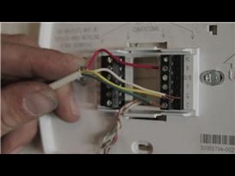
Inside the air conditioner thermostat, there are a number of metal screws on connections. This thin thermostat wire is to adjust the temperature of cooling mode. A detailed diagram illustrating where the wires go for 5 wire air conditioner and heating system control. 1) disconnect all power before servicing. Our wiring diagrams section details a selection of key wiring diagrams focused around typical sundial s and y plans.
Find Out Here Air Conditioner thermostat Wiring Diagram ... from worldvisionsummerfest.com Split system air conditioner (outdoor section) three phase. On central units the thermostat on the wall sends 24 volts (24 volts comes from a transformer in the blower housing) to relays and contactors that switch the below we have thumbnail pictures with installation instructions, wiring diagram, mode of operation & specifications. Red wire for air conditioner control power (hot). Components of air conditioner wiring diagram and some tips. Here you will find the basics wiring diagram of thermostat with air conditioner, heat pump, and blower fan. Lastly, resource and related links to help you with wiring and installing a thermostat. These screws and connections are called terminals, and are the points at which electric wires from your ac unit are joined to the thermostat. Remove 2 screws which fasten the thermostat.
(refer to section 3) 3.
As shown in the diagram the y terminal is where the signal to the cooling air conditioner signal is connected. Contains all the essential wiring diagrams across our range of heating controls. Air conditioner, ptac (packaged terminal air conditioner), heat pump. Remove 2 screws which fasten the thermostat. Before doing any work on the thermostat and wiring take a picture off the wires and their connections, or write them. Thermostat wiring consists of wires that connect the transformer to the system relays. Repair or replace loose terminal. (see figure 27) 4 connect wire. The thermostat is very useful devices for hvac installation in our house. Refer to wiring diagram for terminal identification. Furnace thermostat wiring falls in the diy category that a handy type person can hook up or fix. The electrical wiring diagrams for typical air conditioning equipment. What makes an air conditioner tick?
Here you will find the basics wiring diagram of thermostat with air conditioner, heat pump, and blower fan. This thin thermostat wire is to adjust the temperature of cooling mode. Also see for universal system air conditioner. Red wire for air conditioner control power (hot). Low voltage thermostat wiring diagrams for heat pumps, electric strip heating, furnaces, air conditioners, boilers, and 750mv gas valves.
Central Air Conditioning Information : How to Wire a ... from i.ytimg.com Firstly, select the warmup thermostat model you are installing. (refer to section 3) 3. Mounting and wiring your new thermostat 4.1 install new thermostat base. Click the icon or the document title to download the pdf. When working with a thermostat the cover can be snapped off to expose the wiring. A detailed diagram illustrating where the wires go for 5 wire air conditioner and heating system control. Split system air conditioner (outdoor section) three phase. Ems si wiring guide and connection description.
Also see for universal system air conditioner.
Inside the air conditioner thermostat, there are a number of metal screws on connections. Car air conditioner electrical wiring. (refer to section 3) 3. The wiring diagram tool below allows you to specify your exact warmup thermostat and heating system configuration. 1) disconnect all power before servicing. Firstly, select the warmup thermostat model you are installing. Low voltage thermostat wiring diagrams for heat pumps, electric strip heating, furnaces, air conditioners, boilers, and 750mv gas valves. Ems si wiring guide and connection description. The electrical wiring diagrams for typical air conditioning equipment. Mounting and wiring your new thermostat 4.1 install new thermostat base. Now that you are armed with a basic. These screws and connections are called terminals, and are the points at which electric wires from your ac unit are joined to the thermostat. Our wiring diagrams section details a selection of key wiring diagrams focused around typical sundial s and y plans.
Let's see how this power flows through the thermostat when the air. Contains all the essential wiring diagrams across our range of heating controls. Mounting and wiring your new thermostat 4.1 install new thermostat base. On central units the thermostat on the wall sends 24 volts (24 volts comes from a transformer in the blower housing) to relays and contactors that switch the below we have thumbnail pictures with installation instructions, wiring diagram, mode of operation & specifications. The main types and equipments in common air conditioning systems were a rotating thermostat switch work as on/off switch for the compressor, its status is depending on what temperature/cooling degree you set it at.
Duo therm thermostat Wiring Diagram Collection from wholefoodsonabudget.com When working with a thermostat the cover can be snapped off to expose the wiring. On central units the thermostat on the wall sends 24 volts (24 volts comes from a transformer in the blower housing) to relays and contactors that switch the below we have thumbnail pictures with installation instructions, wiring diagram, mode of operation & specifications. Lastly, resource and related links to help you with wiring and installing a thermostat. Thermostat wiring consists of wires that connect the transformer to the system relays. Click the icon or the document title to download the pdf. Remove 2 screws which fasten the thermostat. Humidifier, dehumidifier, erv/hrv ventilator use the wiring diagram and code to attach the wires to the terminals on the thermostat that correspond to the connections on the furnace or air handler. Let's see how this power flows through the thermostat when the air.
When working with a thermostat the cover can be snapped off to expose the wiring.
Here you will find the basics wiring diagram of thermostat with air conditioner, heat pump, and blower fan. Let's see how this power flows through the thermostat when the air. Our wiring diagrams section details a selection of key wiring diagrams focused around typical sundial s and y plans. Also see for universal system air conditioner. Leveling thermostat leveling is for appearance only outdoor equipment no air conditioner / no heat pump single stage air conditioner two stage air conditioner single stage heat pump two stage heat pump. .charging, furnaces, heat pumps, air conditioning, electrical troubleshooting, wiring, refrigeration cycle, superheat and subcooling, gas lines, & more! This terminal will call for the need to cool the room when the set temperature is lower than the room temperature. Air conditioner, ptac (packaged terminal air conditioner), heat pump. Can i install an ecobee smartthermostat with voice control on my ecobee4 or ecobee3 lite setup? Car air conditioner electrical wiring. Red wire for air conditioner control power (hot). Furnace thermostat wiring falls in the diy category that a handy type person can hook up or fix. Thermostat installation & wiring diagrams.